Sunday 26 February 2012

Final Week of Project

We have performed the simulation to find the approximate RCS of the Lockheed C-5 Galaxy by breaking down the aircraft into numerous points as shown in Figure 1, and each point represents a simple shape.

Figure 1. Representations of the aircraft's structure (Note that there are some changes compared to the previous post)

Simplifying assumptions:

1. Sphere                              : Point 1.
2. Cylinder                             : Point 2, 3, 4, 5, 6, 15 and 16.
3. Rectangular flat plate          : Point 11, 12, 13, 14, 21, and 22.
4. Rectangular dihedral corner : Point 7, 8, 9, 10, 17, 18, 19 and 20.

The MATLAB program was as shown in Figure 2, 3 and 4:

Figure 2.

Figure 3.

Figure 4.

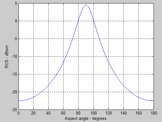
The results obtained from the simulations were as shown in Figure 5 and 6:

Figure 5. Simulation result with 3.75 MHz frequency.

Figure 6. Simulation result with 50 MHz frequency.

The results shown in Figure 5 and 6 was similar to the typical RCS diagrams. A more accurate result was given by the simulation with higher frequency, because higher frequency provides higher resolution of the RCS contribution by each components. The largest magnitude of RCS or ‘spikes’ were normally produced by the structure’s extremities, such as the tip of the wing.

However, the accuracy of this results was not able to be verified, since the real RCS values of most military aircrafts were kept secret from the public.

Furthermore, our simulation was performed with a lot of simplifying assumptions in terms of the shapes and the aircraft's dimension (most of the length of each components were just a rough assumptions). Needless to say, there might be some mistakes in our calculations and program codes.   

Nevertheless, this mini project gave us a very good understanding of the basics of RCS and the insight of radar's operating principle. It is our fervent hope that one day we could perform a proper RCS simulation and perhaps pursue our future career in radar engineering.

Saturday 18 February 2012

Third Week of Project

We are currently trying to simulate the RCS of a complex object. The complex object is broken down into several components which consist of simple shaped objects as shown in Figure 1. Then the individual RCS of each components are summed together to obtain the approximate value of the total RCS. This method is not very accurate but it provides a good overview of the RCS of a complicated structure.

Figure 1. RCS of Structures. (Taken from J. F. Ralph, Avionics AERO230 Lecture Notes, University of Liverpool, 2012)

For this project, we chose to simulate the RCS of Lockheed C-5 Galaxy, a military transport aircraft as shown in Figure 2.

Figure 2. Diagram of Lockheed C-5 Galaxy (Taken from http://www.globalsecurity.org/military/systems/aircraft/c-5-specs.htm)


We represent the aircraft with series of points as shown in Figure 3 to indicate our rough assumption of the objects' shapes.

Figure 3. A sketch of the structure's representation.

Assumptions made:
1) Sphere                                : Point 1
2) Cylinder                              : Point 2, 3, 4, 5, 6, 19 & 20
3) Rectangular Flat Plate         : Point 11, 12, 13, 14, 15, 16, 17, 18, 25, 26, 27, 28
4) Rectangular Dihedral Corner : Point 7, 8, 9 10, 21, 22, 23, 24

Then, the approximate total RCS can be calculated using the formula that is shown in Figure 3.

Saturday 11 February 2012

Second Week of Project

We have performed several simulations involving simple shapes such as ellipsoid and cylinder. In this post, we only show the ellipsoid as it is the easiest shape to be studied in order to understand the effect of radar direction to the target's RCS, which is the effective reflective area. If the target's RCS is large, it will be easier for the target to be detected by radar.  

Figure 1. Ellipsoid. (Taken from Mahafza, Bassem R, MATLAB Simulations for Radar Systems Design, CRC Press/Chapman & Hall, 2004.)
As shown in Figure 1, the direction of receiving radar is represented by the vertical/aspect angle, theta, and the horizontal angle, phi.

First, we simulated the condition where the length b was longer than a, and phi at zero degree. The result was as shown in Figure 2.

Figure 2.

Figure 2 shows that the RCS kept increasing when the aspect angle increase, but then started to decrease after 90 degree. In other word, the reflected power was the largest at the middle of the ellipsoid.

Then, we made the radar direction to face the ellipsoid at the direction of y axis by changing phi to 90 degree and the result was as shown in Figure 3.

Figure 3.

Figure 3 shows that the maximum RCS has decreased compared to the previous simulation. This was because the reflective surface area by looking at the y axis is smaller compared to x axis.

After that, we made the length a to be equal to length b. Then, we ran the simulation at phi equal to zero and 90 degree and the result for both test was as shown in Figure 4 and Figure 5 respectively.

Figure 4.

Figure 5.


Figure 4 and Figure 5  shows that the result for both simulation was just the same and target's RCS was no longer affected by the changes of phi. This was because the equal length of a and b caused the reflective surface area to remained the same in any horizontal direction of the radar.

Finally, we set the length of a, b and c to be equal in order to produce a symmetrical sphere as in Figure 6 and the result of the simulation was as shown in Figure 7.

Figure 6. Sphere. (Taken from Mahafza, Bassem R, MATLAB Simulations for Radar Systems Design, CRC Press/Chapman & Hall, 2004.)

Figure 7.
Figure 7 shows that the RCS remained constant in any vertical or horizontal direction of radar because the reflective surface area of a sphere is the same in any direction.

Wednesday 1 February 2012

First Week of Project (cont.)

We found another good learning resources to gain further understanding. It was a series of video lectures from the MIT regarding the basic concepts of radar systems. They were very useful for newbies such as us.

The link to those videos: http://ocw.mit.edu/resources/res-ll-001-introduction-to-radar-systems-spring-2007/

Monday 30 January 2012

First Week of Project

Our plan for the first week is to study the theories behind Radar Cross Section

Things that have been done so far:

1) Background research.
     a) University's library e-book (Title: MATLAB Simulations for Radar Systems Design by Mahafza, Bassem R)
     b) Lecture notes (Aero 230 Avionic Systems by Dr. J. F. Ralph)